Home
› Engine Starter Motor Diagram / Pre Engaged Lucas Starter Motor Electrical Connection : A starter solenoid is a combination of solenoid and switches (full name:
Engine Starter Motor Diagram / Pre Engaged Lucas Starter Motor Electrical Connection : A starter solenoid is a combination of solenoid and switches (full name:
Engine Starter Motor Diagram / Pre Engaged Lucas Starter Motor Electrical Connection : A starter solenoid is a combination of solenoid and switches (full name:. The powerful electric starter motor does the turning. A wiring diagram is a simplified standard pictorial representation of an electrical circuit. Starter test / starter solenoid test / starter motor testtroubleshooting, diagnosis, repa. Small block chevy 305 starter wiring help in chevy starter wiring diagram by admin through the thousands of pictures on the net regarding chevy starter. Click on the image to enlarge, and then save it to your computer by right clicking on the image.
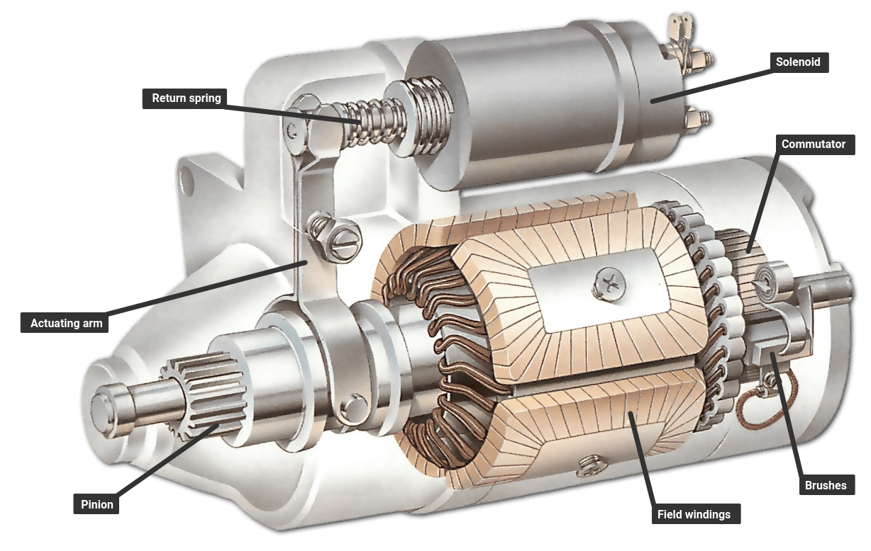
How to wire a motor starter | library.automationdirect throughout starter motor diagram wiring, image size 576 x 511 px, and to view image details please click the image. And finally we upload it on our website. It does so, by disengaging its housing (which rotates with the motor armature) from an inner race which is combined with the pinion gear. In this video we cover the differences between a factory gm starter and an after market high torque mini starter. A starter solenoid is a combination of solenoid and switches (full name:
Car Starter High Res Stock Images Shutterstock from image.shutterstock.com And finally we upload it on our website. The result is a rotating crank and engine cycle can be triggered to work continuously. Most starter motor wiring circuits follow the same procedure though configurations may vary. As soon as the engine begins to run, it got disconnected from the engine, which now relies on the combustion process. In this case, neutral white is carried through to the motor bypassing the starter altogether. Click for a larger photo. •uses a powerful electric motor to drive the engine at about 200 rpm (fast enough to allow the fuel and ignition systems to operate). 240 volt, 1 phase motors should use a 2 pole starter.
Based on the above wiring diagram, you need the following:
Starter test / starter solenoid test / starter motor testtroubleshooting, diagnosis, repa. 240 volt, 1 phase motors should use a 2 pole starter. Starter solenoid wiring diagram chevy sample. The starter bendix gear is designed with a one way clutch which enables the starter motor to freewheel as the engine starts while forcing the gear back into the starter motor when it loses momentum. The starter, which operates with the help of a solenoid, can generate a significant amount of horsepower for a limited time. L1 is line 1 in and should be connected to one of the hot wires, l2 is line 2 in. Electrical checks are made with a circuit tester or test lamp or with a voltmeter. •drives the engine through a pinion gear engaged with a. Small block chevy 305 starter wiring help in chevy starter wiring diagram by admin through the thousands of pictures on the net regarding chevy starter. Starter motor once the engine has been started. How to wire a motor starter | library.automationdirect throughout starter motor diagram wiring, image size 576 x 511 px, and to view image details please click the image. A starter or starter motor is an electrical device that used to rotate (crank) internal combustion engines so as to initiate the engine's operation under its own power. It reveals the parts of the circuit as streamlined forms, and the power and also signal links between the devices.
A starter solenoid is a combination of solenoid and switches (full name: Tion diagrams, show the actual connection points for the wires to the components and terminals of the controller. It is a momentary contact position usually on the key switch. Small block chevy starter wiring diagram. Many good image inspirations on our internet are the best image selection for diesel engine starter wiring diagram.
Starter Diagnosis from aa1car.com The result is a rotating crank and engine cycle can be triggered to work continuously. It does so, by disengaging its housing (which rotates with the motor armature) from an inner race which is combined with the pinion gear. It reveals the parts of the circuit as streamlined forms, and the power and also signal links between the devices. Click for a larger photo. A wiring diagram is a simplified standard pictorial representation of an electrical circuit. Universal ignition switch wiring diagram elegant engine wiring tractor diesel ignition switch wiring diagram. This wiring should not be used on 240 volt circuits. Relay wiring diagram for starter fresh wiring diagram starter.
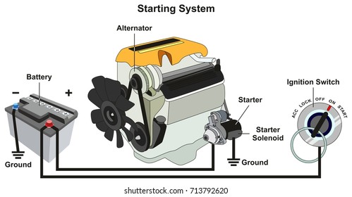
The working principle of starter motor is to rotate the engine crankshaft via flywheel using electric motor circuit.
A mechanical check to see if the starter pinion gear. Electrical checks are made with a circuit tester or test lamp or with a voltmeter. A wiring diagram is a simplified standard pictorial representation of an electrical circuit. Based on the above wiring diagram, you need the following: If not, the structure will not work as it ought to be. They show the relative location of the components. How a car starting system works: It reveals the parts of the circuit as streamlined forms, and the power and also signal links between the devices. How to test / troubleshoot / check a starter for correct operation: A starter solenoid is a combination of solenoid and switches (full name: Click for a larger photo. The starter bendix gear is designed with a one way clutch which enables the starter motor to freewheel as the engine starts while forcing the gear back into the starter motor when it loses momentum. We collect a lot of pictures about diesel engine starter wiring diagram.
Universal ignition switch wiring diagram elegant engine wiring tractor diesel ignition switch wiring diagram. A starter or starter motor is an electrical device that used to rotate (crank) internal combustion engines so as to initiate the engine's operation under its own power. •drives the engine through a pinion gear engaged with a. Collection of starter solenoid wiring diagram chevy. Through the thousands of photographs on the net with regards to chevy 350 engine wiring diagram, choices the best selections using ideal quality only for you all, and this photographs is usually one among images choices in your best photographs gallery with regards to chevy 350 engine wiring diagram.i am hoping you may as it.
How The Starting System Works How A Car Works from www.howacarworks.com Starter motor once the engine has been started. A starter or starter motor is an electrical device that used to rotate (crank) internal combustion engines so as to initiate the engine's operation under its own power. Spring loaded wedged rollers are used. How a starter works & diy repair. Starter the starter motor drives the engine through a pinion gear that engages the ring gear on the flywheel. How to wire a motor starter | library.automationdirect throughout starter motor diagram wiring, image size 576 x 511 px, and to view image details please click the image. Starter solenoid wiring diagram chevy sample. As soon as the engine begins to run, it got disconnected from the engine, which now relies on the combustion process.
L1 is line 1 in and should be connected to one of the hot wires, l2 is line 2 in.
The working principle of starter motor is to rotate the engine crankshaft via flywheel using electric motor circuit. Small block chevy starter wiring diagram. Many good image inspirations on our internet are the best image selection for diesel engine starter wiring diagram. How to test / troubleshoot / check a starter for correct operation: It is one of the main components of the car starter (motor, starter bendix drive, starter solenoid) as we all know, the starting of the engine requires external support, and the car starter is playing this role. Variety of kohler engine wiring schematic. Collection of starter solenoid wiring diagram chevy. The starter, which operates with the help of a solenoid, can generate a significant amount of horsepower for a limited time. Its shaft carries a small pinion ( gear wheel) which engages with a large gear ring around the rim of the engine flywheel. A wiring diagram is a simplified standard pictorial representation of an electrical circuit. In this video we cover the differences between a factory gm starter and an after market high torque mini starter. Some owners manuals have a diagram of the engine, though it is not a certainty that the starter will be labeled. How a car starting system works: