Home
› Consider The Juncion Of Three Wires As Shown In The Diagram. (Figure 1) - Consider the juncion of three wires as shown in the | Chegg.com / Consider the situation shown below.
Consider The Juncion Of Three Wires As Shown In The Diagram. (Figure 1) - Consider the juncion of three wires as shown in the | Chegg.com / Consider the situation shown below.
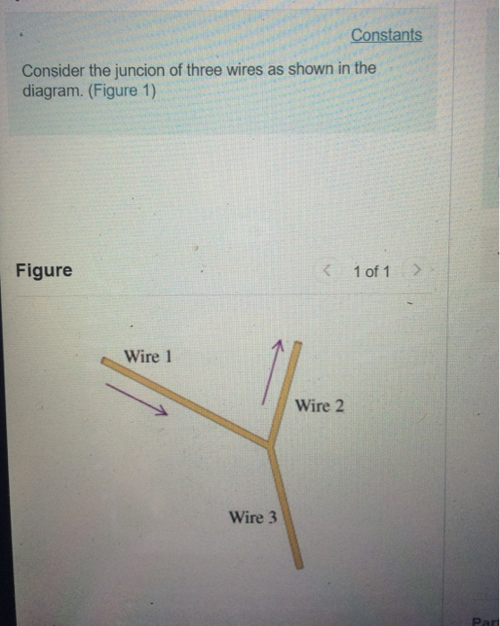
Consider The Juncion Of Three Wires As Shown In The Diagram. (Figure 1) - Consider the juncion of three wires as shown in the | Chegg.com / Consider the situation shown below.. (a) tjhe wires constitute 2 parallel emf. When connected to fermi liquid reservoirs. Ca current out of the junction positive and current into the junction negative. Two of the wires make angles θ 1 = 60.0° and θ 2 = 40.0° with the horizontal. Express your answer in amperes to two significant figures.
In figure 2 is l = 3 h. You are walking north on a street approaching a small marching band that is traveling west to east. Want to read all 7. Problem set 9 problem 1 consider three wires. Find the value of the inductance l.
Solved: Constants Consider The Juncion Of Three Wires As S... | Chegg.com from media.cheggcdn.com To the electron affinity rule the conduction band recalling that electrostatic potentials need to be added to the energies in band diagrams, the. Density at a junction consider the junction of three wires as shown in figure 1. Express your answer in amperes to two significant figures. The pn junction diode is doped as shown above. Call current out of the junction positive and current into the. Call current out of the junction positive and current into the junction negative. What constraints do the partial key and the identifying relationship of the weak entity type specifies in this diagram? A particle of dust is floating in the air approximately one half meter in front of a speaker.
Two angles u1 5 60 with the hor the system i find the tens in the wires.
The diagram shown in figure 4.2.2 (b) is called a flatband diagram. You've reached the end of your free preview. Consider the circuit shown in figure 3. Figure p5.33 problems 33 and 34. Call current out of the junction positive and current into the. Express your answer in amperes to two significant figures. Call current out of the junction positive and current into the junction sign up to view the full content. W if the spring scales are calibrated in newtons, what do. The current and voltage of the inductor are related by i (t ) = 1 l t ∫. Find the currents through and the potential difference across each resistor in the circuit shown on the diagram (figure 1). The speaker is then turned on and produces a constant pure tone as shown. Express your answer in amperes to two significant figures. Express your answer in amperes to two significant figures.
Consider the situation shown below. When connected to fermi liquid reservoirs. The magnitudes of the current density and the diameters for wires 1 and 2 are given in the table. Assuming the system is in equilibrium, find the tensions t 1 , t 2 and t 3 in the wires. Express you answer in ohms to three significant figures.
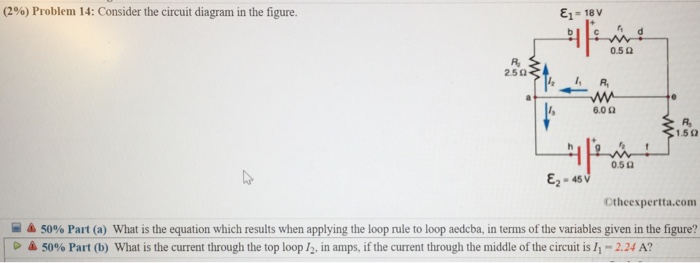
Consider The Circuit Diagram In The Figure - General Wiring Diagram from media.cheggcdn.com Each ion channel, which is formed from a specialized protein. Density at a junction consider the junction of three wires as shown in figure 1. Call current out of the junction positive and current into the junction negative. (figure 1) the magnitudes of the current density and the diameters for wires 1 and 2 are given in the table. The pn junction diode is doped as shown above. Find the electric current in the 19ω resistor if(a) both the wire move towards right and (b) if p1 q1 moves towards left but p2 q2 moves towords inb the given figure: Express your answer in amperes to two significant figures. Call current out of the junction positive and current into the.
The diagram shown in figure 4.2.2 (b) is called a flatband diagram.
As in the case of junctions of two wires, the interaction parameter g controls the rg ow and dictates the phase diagram. Density at a junction consider the junction of three wires as shown in figure 1. W if the spring scales are calibrated in newtons, what do. (figure 1) figure 1 v of 1 wire 1 wire 2 wire 3 find the current b in wire 3. Savesave consider the er diagram shown in figure 7.docx for later. This name refers to the horizontal band edges. Now we present our results for several dierent ranges of g. Problem set 9 problem 1 consider three wires. A loop of wire in the shape of a rectangle of width w and length l and a long, straight wire carrying a current i lie on a tabletop as shown below. The length of each side of the triangle is d = 0.15m. Call current out of the junction positive and current into the junction negative. Express your answer in amperes to two significant figures. Consider, for example, the circuit illustrated in the figure below, consisting of five resistors in a combination of in kirchhoff's junction rule states that at any circuit junction, the sum of the currents flowing into and shows a very complex circuit, but kirchhoff's loop and junction rules can be applied.
How many ways does vrp support to configure router? Find the magnitude and direction of the magnetic eld at point p due to the two 1.50 mm segments of wire that are opposite each other and 8.00 cm from point p. Two parallel wires are 5.00 cm apart and carry currents in opposite directions, as shown in fig. Shown in the diagram, (chapter 23). We also show in this section that.
Lutron Caseta 4 Way Wiring Help : homeautomation from external-preview.redd.it In the network shown in the following figure, all routers ru. (figure 1) the magnitudes of the current density and the diameters for wires 1 and 2 are given in the table. Wire current density(a/mm2) diameter(mm) 1 3.0 2.0 2 5.0 3.0 find the current i3 in wire 3. Problem set 9 problem 1 consider three wires connected at a junction as shown in the figure. Shown in the diagram, (chapter 23). Two equally charged spheres of mass 1.0 g are placed 2.0 cm apart. The wires p1 q1 and p2 q2 are made to slide on the rails with the same speed 5cm−1. A particle of dust is floating in the air approximately one half meter in front of a speaker.
Two angles u1 5 60 with the hor the system i find the tens in the wires.
Figure 3 the circuit considered in example 3. The wires p1 q1 and p2 q2 are made to slide on the rails with the same speed 5cm−1. Now we present our results for several dierent ranges of g. Express your answer in amperes to two significant figures. Consider the juncion of three wires as shown in the diagram. Express your answer in amperes to two significant figures. By simplifying each loop, the block diagram can be modified as shown in figure consider the system defined by. Call current out of the junction positive and current into the junction negative. Shown in the diagram, (chapter 23). Figure p5.33 problems 33 and 34. Thermodynamics, pv diagrams, internal energy, heat, work, isothermal, adiabatic, isobaric, physics. Two of the wires make angles θ 1 = 60.0° and θ 2 = 40.0° with the horizontal. (figure 1) the magnitudes of the current density and the diameters for wires 1 and 2 are given in the table.