Furnace Thermostat Wiring Diagram - Goodman Furnace Thermostat Wiring Diagram / Honeywell Rth9580wf To Goodman Janitrol Gmp075 3 ... : Installation screws and wiring diagram included.. At the thermostat, connect the clamp to the new wire bundle about 8" from the wall, cut the wiring bundle, and remove the old thermostat mounting base. I explain what each of the letter t. Installation screws and wiring diagram included. The second wiring diagram showing a heat pump system. It is a red wire and comes from the transformer usually located in the air handler for split systems, but you may find the transformer in the condensing unit.
The second wiring diagram showing a heat pump system. Attach the wires to the terminals on the furnace using the color code and diagram provided with the thermostat and/or the furnace or air handler. Finally, the third thermostat diagram showing the average type of split system with an air conditioner or gas or oil furnace used for heating. Standard ac with standard furnace control wiring standard furnace standard thermostat standard a/c condenser 1st stage heat (white) 24 volt+ fan only operation common air conditioning ac contactor control board 1 this diagram is to be used as reference for the low voltage control wiring of your heating and ac system. In this hvac installation training video, i show how to wire the low voltage thermostat wires into a furnace and ac unit.
Replaced Thermostat, now AC stays on with Furnace - DoItYourself.com Community Forums from www.doityourself.com Oct 25, 2014 · furnace control board wiring diagram doesn't seem to clearly indicate the attach point at the furnace end. Installation screws and wiring diagram included. At the thermostat, connect the clamp to the new wire bundle about 8" from the wall, cut the wiring bundle, and remove the old thermostat mounting base. This dometic analog thermostat controls cool/off/furnace, fan on/auto, and hi/low functions. It is a red wire and comes from the transformer usually located in the air handler for split systems, but you may find the transformer in the condensing unit. Attach the wires to the terminals on the furnace using the color code and diagram provided with the thermostat and/or the furnace or air handler. In this hvac installation training video, i show how to wire the low voltage thermostat wires into a furnace and ac unit. With the top thermostat wiring diagram showing an air conditioning system.
Installation screws and wiring diagram included.
The thermostat is the control device that provides a simple user interface with the internal workings of your homes climate control system. Attach the wires to the terminals on the furnace using the color code and diagram provided with the thermostat and/or the furnace or air handler. Finally, the third thermostat diagram showing the average type of split system with an air conditioner or gas or oil furnace used for heating. It is a red wire and comes from the transformer usually located in the air handler for split systems, but you may find the transformer in the condensing unit. The color of wire r is usually red and c is black. The second wiring diagram showing a heat pump system. In this hvac installation training video, i show how to wire the low voltage thermostat wires into a furnace and ac unit. Oct 25, 2014 · furnace control board wiring diagram doesn't seem to clearly indicate the attach point at the furnace end. At the thermostat, connect the clamp to the new wire bundle about 8" from the wall, cut the wiring bundle, and remove the old thermostat mounting base. As shown in the diagram, you will need to power up the thermostat and the 24v ac power is connected to the r and c terminals. I explain what each of the letter t. This dometic analog thermostat controls cool/off/furnace, fan on/auto, and hi/low functions. Standard ac with standard furnace control wiring standard furnace standard thermostat standard a/c condenser 1st stage heat (white) 24 volt+ fan only operation common air conditioning ac contactor control board 1 this diagram is to be used as reference for the low voltage control wiring of your heating and ac system.
With the top thermostat wiring diagram showing an air conditioning system. At the thermostat, connect the clamp to the new wire bundle about 8" from the wall, cut the wiring bundle, and remove the old thermostat mounting base. Installation screws and wiring diagram included. The second wiring diagram showing a heat pump system. I explain what each of the letter t.
Furnace Thermostat Wiring and Troubleshooting - HVAC How To from www.hvachowto.com It is a red wire and comes from the transformer usually located in the air handler for split systems, but you may find the transformer in the condensing unit. Standard ac with standard furnace control wiring standard furnace standard thermostat standard a/c condenser 1st stage heat (white) 24 volt+ fan only operation common air conditioning ac contactor control board 1 this diagram is to be used as reference for the low voltage control wiring of your heating and ac system. Oct 25, 2014 · furnace control board wiring diagram doesn't seem to clearly indicate the attach point at the furnace end. I explain what each of the letter t. These two connections will ensure that there is power to the. Installation screws and wiring diagram included. The thermostat is the control device that provides a simple user interface with the internal workings of your homes climate control system. Attach the wires to the terminals on the furnace using the color code and diagram provided with the thermostat and/or the furnace or air handler.
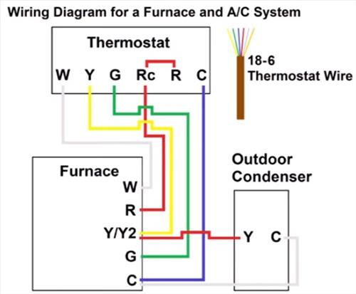
As shown in the diagram, you will need to power up the thermostat and the 24v ac power is connected to the r and c terminals.
The thermostat is the control device that provides a simple user interface with the internal workings of your homes climate control system. These two connections will ensure that there is power to the. As shown in the diagram, you will need to power up the thermostat and the 24v ac power is connected to the r and c terminals. Attach the wires to the terminals on the furnace using the color code and diagram provided with the thermostat and/or the furnace or air handler. In this hvac installation training video, i show how to wire the low voltage thermostat wires into a furnace and ac unit. At the thermostat, connect the clamp to the new wire bundle about 8" from the wall, cut the wiring bundle, and remove the old thermostat mounting base. Oct 25, 2014 · furnace control board wiring diagram doesn't seem to clearly indicate the attach point at the furnace end. With the top thermostat wiring diagram showing an air conditioning system. The color of wire r is usually red and c is black. The second wiring diagram showing a heat pump system. It is a red wire and comes from the transformer usually located in the air handler for split systems, but you may find the transformer in the condensing unit. Installation screws and wiring diagram included. Color of wire and termination:
With the top thermostat wiring diagram showing an air conditioning system. Oct 25, 2014 · furnace control board wiring diagram doesn't seem to clearly indicate the attach point at the furnace end. The second wiring diagram showing a heat pump system. C is known as the common terminal. As shown in the diagram, you will need to power up the thermostat and the 24v ac power is connected to the r and c terminals.
Room thermostat wiring diagrams for HVAC systems from inspectapedia.com Color of wire and termination: The second wiring diagram showing a heat pump system. Installation screws and wiring diagram included. I explain what each of the letter t. C is known as the common terminal. In this hvac installation training video, i show how to wire the low voltage thermostat wires into a furnace and ac unit. As shown in the diagram, you will need to power up the thermostat and the 24v ac power is connected to the r and c terminals. The thermostat is the control device that provides a simple user interface with the internal workings of your homes climate control system.
Standard ac with standard furnace control wiring standard furnace standard thermostat standard a/c condenser 1st stage heat (white) 24 volt+ fan only operation common air conditioning ac contactor control board 1 this diagram is to be used as reference for the low voltage control wiring of your heating and ac system.
Oct 25, 2014 · furnace control board wiring diagram doesn't seem to clearly indicate the attach point at the furnace end. I explain what each of the letter t. The thermostat is the control device that provides a simple user interface with the internal workings of your homes climate control system. C is known as the common terminal. The color of wire r is usually red and c is black. Attach the wires to the terminals on the furnace using the color code and diagram provided with the thermostat and/or the furnace or air handler. Installation screws and wiring diagram included. This dometic analog thermostat controls cool/off/furnace, fan on/auto, and hi/low functions. In this hvac installation training video, i show how to wire the low voltage thermostat wires into a furnace and ac unit. These two connections will ensure that there is power to the. Standard ac with standard furnace control wiring standard furnace standard thermostat standard a/c condenser 1st stage heat (white) 24 volt+ fan only operation common air conditioning ac contactor control board 1 this diagram is to be used as reference for the low voltage control wiring of your heating and ac system. At the thermostat, connect the clamp to the new wire bundle about 8" from the wall, cut the wiring bundle, and remove the old thermostat mounting base. As shown in the diagram, you will need to power up the thermostat and the 24v ac power is connected to the r and c terminals.